

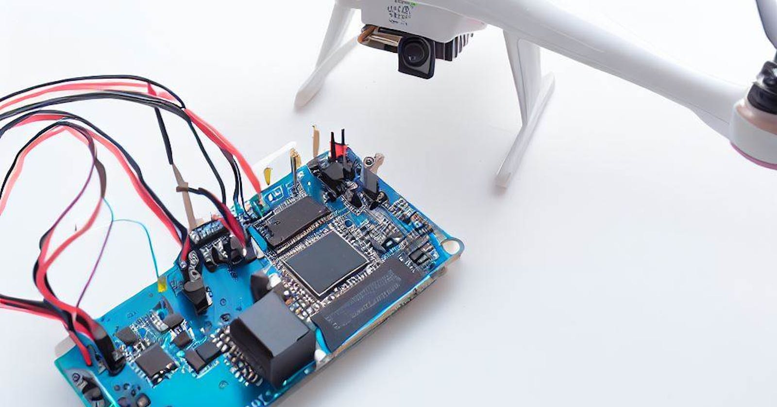
Mapping the Skies: Drone Flying Route Planner by using the GY-NEO6MV2 module and an Arduino board


The GY-NEO6MV2 GPS module is a small, low-cost GPS module that can be easily integrated with microcontrollers like Arduino. It can receive signals from multiple satellites and use this information to calculate precise coordinates of the module's location. This module features a ceramic antenna that helps it receive GPS signals even in environments with weak signal strength, and it can be powered using a 5V power source. The GY-NEO6MV2 module communicates with the microcontroller in a serial protocol that allows for easy integration with Arduino or other boards. With its low-cost and small form factor, the GY-NEO6MV2 GPS module is a popular choice for hobbyists and makers who want to add GPS capabilities to their projects.
These are some project ideas that you can make using the GY-NEO6MV2 GPS module:
Drone Flying Route Planner: By using the GY-NEO6MV2 module and an Arduino board, you can make a drone flying route planner that plans the optimal flying route for your drone based on the GPS coordinates. You can use the TinyGPS++ library to parse the GPS data and plan the flying route using a pathfinding algorithm like Dijkstra's algorithm or A* algorithm.
Real-time GPS Tracker: Using the GY-NEO6MV2 module and an Arduino board, you can make a real-time GPS tracker that can track the location of any object, person, or vehicle. You can connect the module to the Arduino board using jumper wires and use the TinyGPS++ library to parse the GPS data. You can then display the location data on an LCD or send it to a remote server using GPRS or Wi-Fi.
GPS Clock: By using the GY-NEO6MV2 module and an Arduino board, you can make a GPS clock that automatically sets the time and date based on the GPS data. You can display the time and date on an LCD or a 7-segment display. This is a great project if you want to learn how to work with real-time clocks (RTC) and GPS data.
Geo-fencing Alarm System: With the GY-NEO6MV2 module and an Arduino board, you can create a geo-fencing alarm system that triggers an alarm when an object moves beyond a specified geographical boundary. For example, you can set up a geo-fence around your home or office, and if someone tries to move your bike or car beyond that area, the alarm will be triggered. You can use the TinyGPS++ library to get the location data and store the boundary coordinates in the Arduino's memory.
GPS Navigation System: By using the GY-NEO6MV2 module, an Arduino board, and an LCD or OLED display, you can make a GPS navigation system for your car or bike. You can store the maps (in bitmap format) in the Arduino's memory and use the GPS data to calculate the current location and direction of the vehicle. You can then display the map and the navigation directions on the screen.
Weather Station: With the GY-NEO6MV2 module and an Arduino board, you can create a weather station that measures the temperature, humidity, and air pressure of your surroundings. You can also add a real-time clock (RTC) module to capture the time and date. You can then store the data in an SD card or send it to a remote server using Wi-Fi or GPRS. This project is a great way to learn how to work with sensors and data logging.
Geo-tagging Camera: With the GY-NEO6MV2 module, an Arduino board, and a camera module, you can make a geo-tagging camera that captures photos and records the GPS data of the location where the photo was taken. You can display the location data on the LCD or OLED display or store it in the camera's memory.
GPS Speedometer: By using the GY-NEO6MV2 module and an Arduino board, you can make a GPS speedometer that measures the speed of your vehicle in real-time. You can use the TinyGPS++ library to get the location data and calculate the speed using the distance and time formulas. You can display the speed on an LCD or OLED display or store it in an SD card.
GPS Data Logger: With the GY-NEO6MV2 module and an Arduino board, you can create a GPS data logger that logs the GPS data of your journey. This project is similar to a GPS navigation system, but instead of showing the map and directions, it stores the GPS data (latitude, longitude, altitude, and time) in an SD card. You can then use this data for analysis or visualization.
Geocaching Tool: By using the GY-NEO6MV2 module and an Arduino board, you can make a geocaching tool that helps you find hidden treasures by providing the coordinates of the hidden location. You can use the TinyGPS++ library to get the location data and display it on an LCD or OLED display. You can also add a distance sensor or LED to help you find the hidden treasure.
You can make a drone flying route planner that plans the optimal flying route for your drone based on the GPS coordinates. You can use the TinyGPS++ library to parse the GPS data and plan the flying route using a pathfinding algorithm like Dijkstra's algorithm or A* algorithm.
Here's a step-by-step guide on how to create a Drone Flying Route Planner using an Arduino board and a GY-NEO6MV2 GPS module:
Materials Required:
Arduino board (e.g., Arduino Uno)
GY-NEO6MV2 GPS module
Motor driver (if using a drone)
Drone frame (if using a drone)
Breadboard and jumper wires
USB cable for Arduino board
Battery pack
Step 1: Wiring the GY-NEO6MV2 GPS module to Arduino
Connect the VCC pin of GPS module to 5V pin of Arduino
Connect the GND pin of GPS module to GND pin of Arduino
Connect the TX pin of GPS module to digital pin 3 (RX pin) of Arduino
Connect the RX pin of GPS module to digital pin 2 (TX pin) of Arduino
Step 2: Install Necessary Libraries
Open the Arduino IDE software and go to Sketch > Include Library > Manage Libraries
Install the TinyGPS++ library which will be used to parse the GPS data coming from the GY-NEO6MV2 module.
Once installed, go to Sketch > Include Library > TinyGPS++
Step 3: Code Implementation
Declare the TinyGPSPlus object which will be used to hold the GPS data that the module will send.
  #include <TinyGPS++.h>
  TinyGPSPlus gpsCoords;
Initialize the GPS module and Serial communication in the
void setup()function.void setup() { Serial.begin(9600); // Initialize Serial communication Serial3.begin(9600); // Initialize GPS module communication with a baud rate of 9600 }Inside the
void loop()function, you can start reading the GPS data by calling thegpsCoordsobject which the GPS data is saved into.void loop() { while (Serial3.available() > 0) { gpsCoords.encode(Serial3.read()); // get the GPS data from the GPS module } }Parse the GPS data and display it on the Serial monitor. The
TinyGPS++library includes some methods likelat(),lng(),satellites(),course(),speed(), and more that will provide the corresponding GPS data in a form that is easy to use.void loop() { while (Serial3.available() > 0) { gpsCoords.encode(Serial3.read()); // get the GPS data from the GPS module } if (gpsCoords.location.isValid()) { Serial.print("Location: "); Serial.print(gpsCoords.location.lat(), 6); Serial.print(", "); Serial.println(gpsCoords.location.lng(), 6); Serial.print("Satellites: "); Serial.println(gpsCoords.satellites.value()); Serial.print("Course: "); Serial.print(gpsCoords.course.deg()); Serial.print(" degrees, "); Serial.print("Speed: "); Serial.print(gpsCoords.speed.mph()); Serial.println(" mph"); } }Step 4: Planning the Optimal Flying Route
Once you have the drone's current GPS coordinates, you can use a pathfinding algorithm like Dijkstra's algorithm or A* algorithm to plan the optimal flying route based on the destination GPS coordinates.
Implement the pathfinding algorithm in the code and calculate the optimal route that the drone should follow to reach the destination.
Based on the optimal route, generate the motor commands (if using a drone) that operate the drone's movement through the waypoints defined.
Implement the commands inside the loop to move the drone to the desired waypoint.
After wiring the GPS module to your Arduino board, Installing necessary Libraries and coding you can now plan the optimal route for your drone to fly.